Altium Project: LED 60 Years INSA
Introduction
As part of our curriculum at INSA Toulouse in the Automatic and Electronic specialty, we completed a comprehensive electronic design project using Altium Designer. The project, titled “LED 60 Years INSA,” aimed to celebrate the school’s 60th anniversary with an innovative and aesthetic lighting device, featuring RGB LEDs controlled via an STM32 microcontroller.
This project covered many technical aspects, from PCB routing to mechanical and software design, allowing us to practice key skills in electronic engineering and embedded systems.
Project Objectives
The objectives of this project were multiple:
- Design an electronic circuit capable of controlling RGB LEDs following a specific functional diagram.
- Create a PCB with Altium Designer that meets electrical and mechanical constraints while optimizing routing.
- Design a 3D enclosure to house the printed circuit board and electronic components using Fusion 360.
- Program an STM32 microcontroller to control the RGB LEDs via an SPI bus.
- Ensure the integration of the whole system into a robust, functional, and aesthetically pleasing system.
Design and Routing with Altium Designer
Component Selection
The first step of the project was to select the appropriate components for the design. We chose:
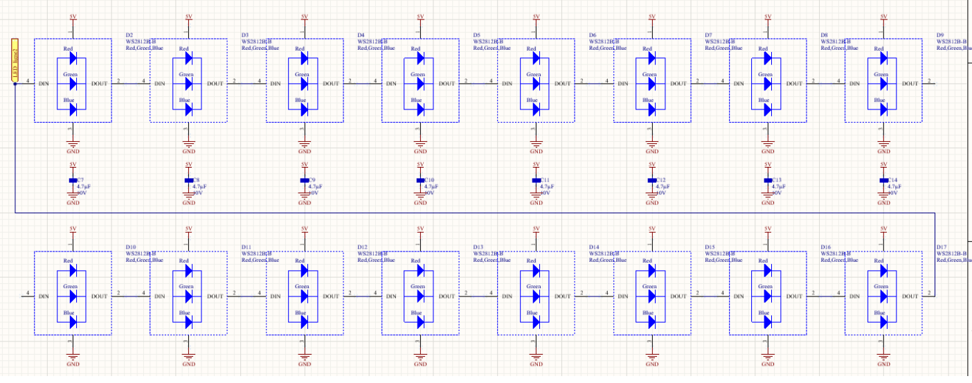
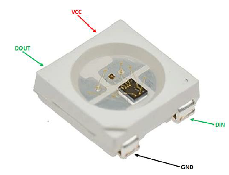
- WS2812B LEDs: Addressable RGB LEDs that can be individually controlled via an SPI bus.
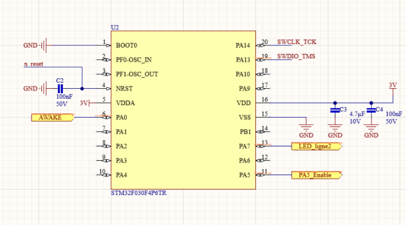
- STM32F103C8T6: An ARM Cortex-M3 based microcontroller, compatible with the SPI protocol and offering good performance for embedded applications.
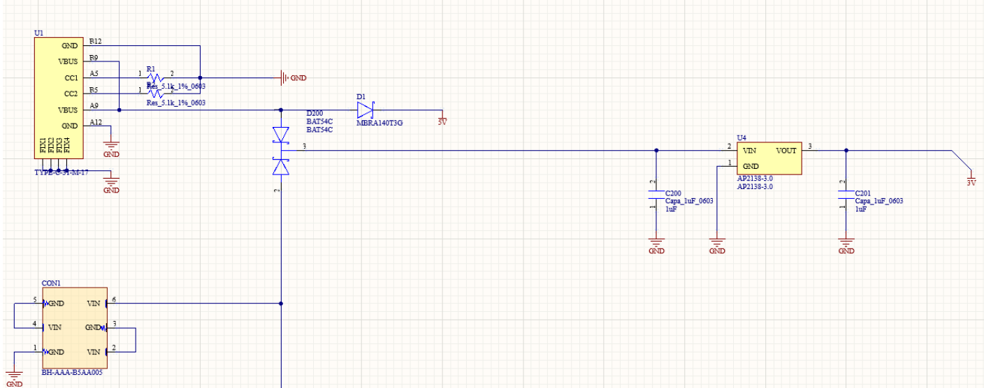
- Power supply components, including voltage regulators and DC-DC converters to manage different power supplies (USB and batteries).
Circuit Schematic
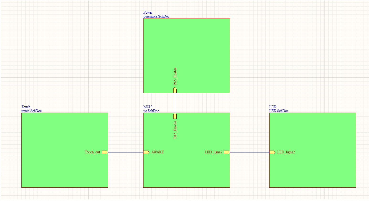
The next step was to create the electronic schematics in Altium Designer. The main subsystems of the circuit include:
- Power supply: Managing different energy sources (USB or batteries) and regulating the voltage to power the LEDs and the microcontroller.
- LED control: Using the SPI bus to send data to the LEDs to manage their color and intensity.
- Programming management: Integrating an interface to program the STM32 via a USB bootloader.
Routing and Optimization
After designing the schematics, we routed the PCB in Altium Designer, considering component placement and track constraints. Key steps in the routing process include:
- Strategic component placement: Positioning the LEDs near the edges for uniform light diffusion and the microcontroller in the center for easy connections.
- Minimizing interference: Following best practices in routing to avoid electromagnetic interference, such as optimizing the width of power tracks and SPI bus data tracks.
- Meeting mechanical constraints: Optimizing the placement of power and programming connectors to match the openings in the 3D enclosure.
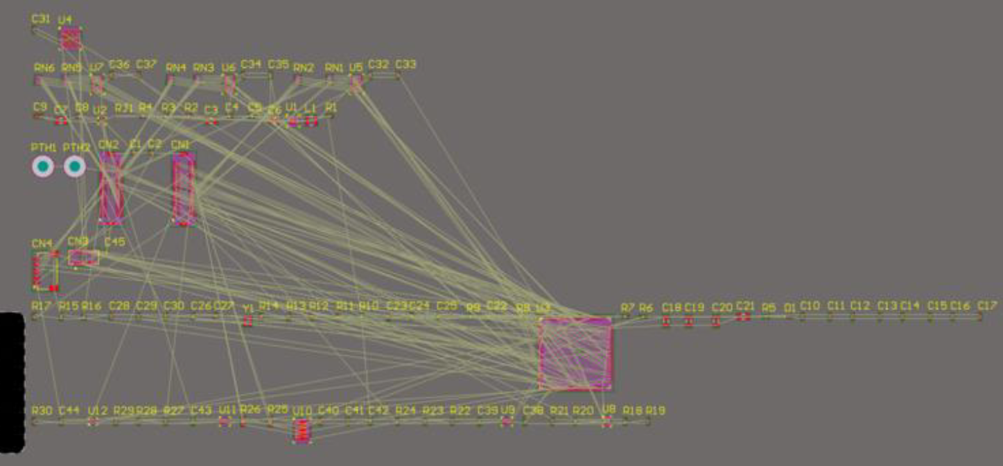
Routing Results
The final routing was done on a double-layer board, allowing separation of critical signals (SPI bus) and power supplies to reduce interference. Adhering to manufacturing constraints was essential, with tracks wide enough to support the current required by the RGB LEDs.
Mechanical Design with Fusion 360
Enclosure Modeling
The enclosure, designed with Fusion 360, was intended to protect and showcase the electronics. Key features include:
- Main body: Supports the PCB and provides space for batteries and USB power.
- Transparent cover: A plexiglass panel to expose the LEDs while protecting them from external elements.
- Battery compartment: A removable section for easy access to the batteries.
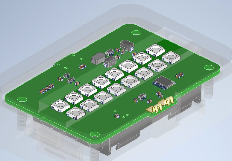
We used 3D printing to create the enclosure, considering precise tolerances to ensure a frictionless assembly.
System Assembly
Once the enclosure was printed, we assembled the different parts of the project. The PCB was securely fixed to the enclosure, electrical connections were verified, and the LEDs were tested to ensure they responded correctly to SPI signals sent by the STM32.
STM32 Microcontroller Programming
Using the SPI Bus to Control the LEDs
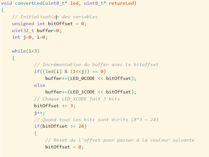
The STM32F103 was programmed to control the WS2812B LEDs via the SPI bus. This communication protocol allows sending RGB data for each LED, individually controlling their color and intensity.
The algorithm we implemented supports converting RGB data into a format understandable by the LEDs. We used the STM32’s SPI interrupts to efficiently manage data transmission, achieving smooth and lag-free lighting.
Added Features
In addition to basic LED control, we added several display modes:
- Color gradient mode: LEDs gradually change color.
- Blinking mode: LEDs turn on and off rhythmically.
- Interaction mode: LEDs react based on data received by the microcontroller, simulating dynamic events (e.g., color change on button press).
Results and Analysis
The “LED 60 Years INSA” project was a technical and aesthetic success. We designed a robust electronic system, fully controlled by an STM32 microcontroller and showcased in a custom-designed enclosure. Using Altium Designer allowed us to produce a functional and optimized PCB, while microcontroller programming provided a wide range of features for the RGB LEDs.
Future Improvements
Some areas for improvement could be explored:
- Routing optimization: Reducing the length of SPI tracks for faster communication.
- Adding sensors: Including light sensors to adjust LED intensity based on the environment.
- Software updates: Developing additional display modes and improving interrupt management efficiency.
Conclusion
This project allowed us to develop essential skills in PCB design with Altium Designer, 3D modeling with Fusion 360, and embedded programming with the STM32. Through a multidisciplinary approach, we created a functional, robust, and aesthetically pleasing product that meets the project’s objectives while celebrating the 60th anniversary of INSA Toulouse.