Introduction
This collection showcases various Arduino-based robotics and electronics projects developed over time, ranging from simple LED control to complex robotic arms and remote-controlled vehicles. These projects demonstrate practical applications of microcontroller programming, motor control, sensor integration, and wireless communication using Arduino platforms.
Project Overview
The projects span multiple domains including:
- Remote-controlled vehicles with Bluetooth control
- Robotic arm prototypes with servo control
- Sensor integration (ultrasonic, infrared, vibration)
- Wireless communication (Bluetooth, ESP32)
- Display interfaces (LCD screens)
- Motor control systems (H-bridge, L298N driver)
Key Technologies
- Microcontrollers: Arduino Uno, Arduino Nano, ESP32-CAM
- Communication: Bluetooth HC-05/HC-06, WiFi (ESP32)
- Sensors: Ultrasonic HC-SR04, infrared sensors, vibration sensors
- Actuators: DC motors, servo motors, LEDs, buzzers
- Motor Drivers: L298N H-Bridge, relay modules
- Displays: LCD 16×2 with I2C interface
Featured Projects
1. Bluetooth-Controlled Remote Car
Project Description
Development of a remote-controlled vehicle controlled via Bluetooth from a smartphone. The car features:
- Four-wheel drive with DC motors
- L298N H-Bridge for bidirectional motor control
- Bluetooth module (HC-05) for wireless communication
- Ultrasonic sensor for obstacle detection
- LED headlights for visibility
- Android app for intuitive control
Hardware Components
Components List:
- Arduino Uno microcontroller
- L298N motor driver module
- 4× DC motors (6V)
- HC-05 Bluetooth module
- HC-SR04 ultrasonic sensor
- 2× LED headlights
- 7.4V Li-Po battery
- Chassis and wheels
Software Implementation
Motor Control Functions:
// Forward motion
void avancer() {
    digitalWrite(enableBridge1, HIGH);
    digitalWrite(MotorForward1, HIGH);
    digitalWrite(MotorReverse1, LOW);
    digitalWrite(enableBridge2, HIGH);
    digitalWrite(MotorForward2, HIGH);
    digitalWrite(MotorReverse2, LOW);
}

// Reverse motion
void reculer() {
    digitalWrite(enableBridge1, HIGH);
    digitalWrite(MotorForward1, LOW);
    digitalWrite(MotorReverse1, HIGH);
    digitalWrite(enableBridge2, HIGH);
    digitalWrite(MotorForward2, LOW);
    digitalWrite(MotorReverse2, HIGH);
}

// Turn right
void droite() {
    digitalWrite(enableBridge2, HIGH);
    digitalWrite(MotorForward2, HIGH);
    digitalWrite(MotorReverse2, LOW);
}

// Turn left
void gauche() {
    digitalWrite(enableBridge1, HIGH);
    digitalWrite(MotorForward1, HIGH);
    digitalWrite(MotorReverse1, LOW);
}

// Stop all motors
void stopp() {
    digitalWrite(enableBridge1, LOW);
    digitalWrite(enableBridge2, LOW);
}
Bluetooth Command Processing:
void loop() {
    if (Serial.available() > 0) {
        Bluetooth = Serial.read();

        switch(Bluetooth) {
            case 'F': avancer(); break;     // Forward
            case 'B': reculer(); break;     // Backward
            case 'R': droite(); break;      // Right
            case 'L': gauche(); break;      // Left
            case 'S': stopp(); break;       // Stop
            case 'W': digitalWrite(phare1, HIGH); break;  // Lights ON
            case 'w': digitalWrite(phare1, LOW); break;   // Lights OFF
        }
    }
}
Features Implemented
- Directional control: Forward, backward, left, right
- Speed control: Variable PWM duty cycle (0-255)
- Obstacle avoidance: Ultrasonic sensor integration
- Lighting system: LED headlights toggle
- Emergency stop: Immediate motor shutdown
- Range: ~10 meters Bluetooth range
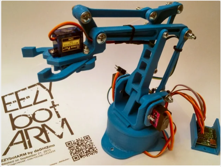
2. Robotic Arm with Servo Control
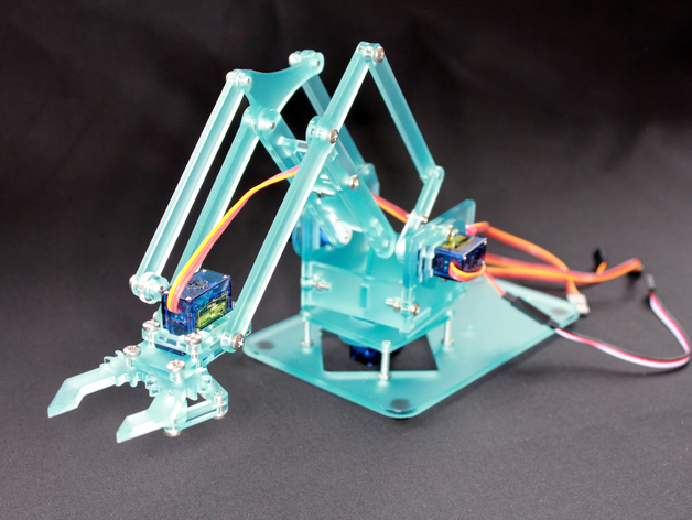
Project Description
Design and development of 3D-printed robotic arms with multiple degrees of freedom, controlled by servo motors and Arduino. The project included:
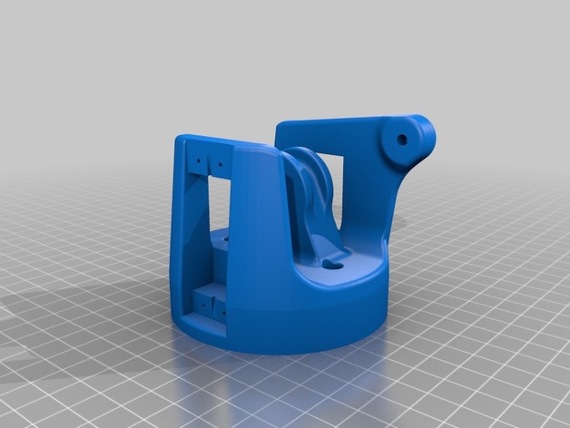
- 3D modeling in CAD software
- STL file generation for 3D printing
- Multi-servo coordination (4-6 servos)
- Gripper mechanism with gear system
- Position control via serial commands or potentiometers
Mechanical Design
The robotic arms were designed with:
- Base rotation: 360° continuous rotation
- Shoulder joint: Vertical movement arm
- Elbow joint: Forward drive arm extension
- Wrist rotation: Horizontal arm orientation
- Gripper: Two-finger claw with gear drive
- Materials: PLA 3D-printed parts, M3 screws, servo brackets
Servo Control System
#include <Servo.h>

Servo servoBase;
Servo servoShoulder;
Servo servoElbow;
Servo servoWrist;
Servo servoGripper;

void setup() {
    servoBase.attach(3);
    servoShoulder.attach(5);
    servoElbow.attach(6);
    servoWrist.attach(9);
    servoGripper.attach(10);

    // Initialize to neutral position
    servoBase.write(90);
    servoShoulder.write(90);
    servoElbow.write(90);
    servoWrist.write(90);
    servoGripper.write(45);
}

void moveToPosition(int base, int shoulder, int elbow, int wrist, int grip) {
    servoBase.write(base);
    delay(15);
    servoShoulder.write(shoulder);
    delay(15);
    servoElbow.write(elbow);
    delay(15);
    servoWrist.write(wrist);
    delay(15);
    servoGripper.write(grip);
}
Applications
- Pick and place operations
- Automated sorting
- Educational robotics demonstrations
- Object manipulation experiments
3. Sensor Integration Modules
Ultrasonic Distance Measurement
const int pinTrig = 6;
const int pinEcho = 7;
long temps;
float distance;

void setup() {
    pinMode(pinTrig, OUTPUT);
    pinMode(pinEcho, INPUT);
    digitalWrite(pinTrig, LOW);
    Serial.begin(9600);
}

void mesureDistance() {
    digitalWrite(pinTrig, HIGH);
    delayMicroseconds(10);
    digitalWrite(pinTrig, LOW);

    temps = pulseIn(pinEcho, HIGH);
    distance = temps * 0.034 / 2;  // Speed of sound: 340 m/s

    Serial.print("Distance: ");
    Serial.print(distance);
    Serial.println(" cm");
}
Infrared Sensor Integration
- Obstacle detection for line-following robots
- Proximity sensing for collision avoidance
- Digital/analog output processing
- Threshold adjustment for different environments
Vibration Sensor
- Shock detection for security systems
- Impact monitoring in mechanical systems
- Digital signal processing with interrupt handling
4. ESP32-CAM Streaming Project
Project Description
Implementation of a WiFi-enabled camera system using the ESP32-CAM module:
- Live video streaming over WiFi
- Web server interface for camera control
- Image capture and storage
- Motion detection capabilities
- Low-power modes for battery operation
Features
- Resolution: Up to 2MP (1600×1200)
- Frame rate: 10-15 FPS for streaming
- WiFi protocols: 802.11 b/g/n
- Web interface: Real-time video display
- Remote control: Pan/tilt with servos (optional)
5. LCD Display Integration
16×2 LCD with I2C Interface
#include <LiquidCrystal_I2C.h>

LiquidCrystal_I2C lcd(0x27, 16, 2);  // Address 0x27, 16 columns, 2 rows

void setup() {
    lcd.init();
    lcd.backlight();
    lcd.setCursor(0, 0);
    lcd.print("Arduino Project");
    lcd.setCursor(0, 1);
    lcd.print("Ready!");
}

void displayMessage(String line1, String line2) {
    lcd.clear();
    lcd.setCursor(0, 0);
    lcd.print(line1);
    lcd.setCursor(0, 1);
    lcd.print(line2);
}
Applications
- System status display
- Sensor data visualization
- User input confirmation
- Menu navigation systems
Technical Challenges and Solutions
Challenge 1: Motor Control Precision
Problem: Inconsistent motor speeds due to battery voltage variations.
Solution: Implemented PWM speed control with voltage monitoring and compensation:
int compensatedSpeed(int desiredSpeed, float batteryVoltage) {
    float nominalVoltage = 7.4;
    int compensated = desiredSpeed * (nominalVoltage / batteryVoltage);
    return constrain(compensated, 0, 255);
}
Challenge 2: Bluetooth Communication Reliability
Problem: Command loss and delayed responses in Bluetooth communication.
Solution:
- Implemented command acknowledgment system
- Added command buffer with FIFO queue
- Increased baud rate to 9600 for stability
- Added error checking and retry mechanism
Challenge 3: Servo Jitter and Noise
Problem: Servo motors exhibited jittering during hold position.
Solution:
- Added capacitors (100µF) across servo power lines
- Implemented separate power supply for servos
- Used
servo.write()only when position changes - Applied software filtering for smooth transitions
Challenge 4: Power Management
Problem: Battery drain and insufficient current for all motors simultaneously.
Solution:
- Calculated total current requirements
- Selected appropriate battery capacity (2200 mAh)
- Implemented staged motor startup
- Added low-voltage cutoff protection
Development Tools and Workflow
Software Tools
- Arduino IDE: Primary development environment
- PlatformIO: Advanced project management
- Serial Monitor: Debugging and testing
- Fritzing: Circuit diagram creation
- Fusion 360: 3D modeling for mechanical parts
Hardware Tools
- Multimeter: Voltage and current measurements
- Oscilloscope: Signal analysis and debugging
- Soldering station: Circuit assembly
- 3D printer: Mechanical part fabrication
- Power supply: Testing with stable voltage
Development Process
- Concept and planning: Define project requirements
- Circuit design: Create schematic and breadboard prototype
- Code development: Write and test firmware incrementally
- Integration testing: Combine hardware and software
- Mechanical assembly: 3D print and assemble parts
- System testing: Validate all functions
- Optimization: Improve performance and reliability
- Documentation: Record specifications and usage
Lessons Learned
Technical Skills Developed
- Microcontroller programming: Arduino C/C++ proficiency
- Hardware interfacing: Sensor and actuator integration
- Communication protocols: UART, I2C, SPI implementation
- Motor control: PWM, H-bridge driver operation
- Mechanical design: CAD modeling and 3D printing
- Debugging techniques: Systematic troubleshooting approach
Best Practices Established
- Modular code structure: Reusable functions and libraries
- Proper documentation: Comments and function descriptions
- Version control: Incremental development with backups
- Power considerations: Separate logic and motor power
- Safety features: Emergency stops and voltage protection
- Testing methodology: Unit tests before system integration
Areas for Future Improvement
- Advanced control algorithms: PID implementation for precise movement
- Sensor fusion: Combining multiple sensors for better accuracy
- Wireless protocols: Transition to WiFi or LoRa for extended range
- Autonomous navigation: Implement pathfinding algorithms
- Computer vision: Integrate OpenCV with ESP32-CAM
- PCB design: Create custom boards for compact integration
Future Project Ideas
Short-term Goals
- Line-following robot with PID control
- Obstacle-avoiding car with multiple sensors
- Bluetooth-controlled robotic arm with position memory
- Weather station with multiple environmental sensors
- Home automation system with relay control
Long-term Aspirations
- Autonomous delivery robot with GPS navigation
- Quadcopter drone with Arduino flight controller
- Bipedal walking robot with servo coordination
- IoT sensor network with cloud data logging
- Robot swarm coordination with inter-robot communication
Conclusion
These Arduino projects represent a journey from basic electronics to complex robotic systems. Each project provided valuable hands-on experience in embedded programming, hardware integration, and system design. The iterative development process, troubleshooting challenges, and continuous learning have built a strong foundation in robotics and electronics.
The skills acquired through these projects are directly applicable to professional embedded systems development, IoT devices, and autonomous robotics. Future projects will build upon this foundation, incorporating more advanced sensors, machine learning algorithms, and sophisticated mechanical designs.