Introduction
Cette partie presente l'etude et la modelisation d'un systeme de commande en boucle fermee pour un moteur a courant continu, avec un accent sur la conception et l'implementation d'un correcteur numerique. Le systeme etudie comprend plusieurs composants cles : le correcteur, le hacheur, le moteur, un transducteur et un conditionneur de signal.
L'objectif principal de ce projet est de concevoir un correcteur numerique pour assurer un controle precis et stable du moteur en courant afin de garantir son couple. Cela implique la modelisation de chaque composant du systeme, la synthese du correcteur et la verification de la stabilite et des performances de la boucle fermee.
Introduction
This part presents the study and modeling of a closed-loop control system for a DC motor, with emphasis on the design and implementation of a digital corrector. The studied system includes several key components: the corrector, the chopper, the motor, a transducer, and a signal conditioner.
The main objective of this project is to design a digital corrector to ensure precise and stable control of the motor in current to ensure its torque. This involves the modeling of each component of the system, the synthesis of the corrector, and the verification of the stability and performance of the closed loop.
Developpement du projet
Modelisation du systeme
Le projet commence par la modelisation du moteur a courant continu et de ses composants associes, y compris le transducteur et le conditionneur de signal. Le moteur est represente par son modele electrique et sa fonction de transfert, tandis que le transducteur est modelise a partir des donnees de sa fiche technique.
Project Development
System Modeling
The project starts with the modeling of the DC motor and its associated components, including the transducer and the signal conditioner. The motor is represented by its electrical model and transfer function, while the transducer is modeled based on data from its datasheet.
La phase suivante implique la conception du correcteur PI (Proportionnel Integral), qui est utilise pour assurer la stabilite et la precision de la commande. Le systeme en boucle ouverte est analyse pour determiner les marges de phase et les constantes de temps, assurant ainsi une reponse dynamique optimale.
Simulation et implementation
Des simulations sont realisees a l'aide de Simulink pour verifier les performances du correcteur et du systeme en boucle fermee. Une transformation bilineaire est appliquee pour modeliser le comportement discret du correcteur lors de son implementation sur un microcontroleur STM32. Une attention particuliere est portee aux temps de reaction, a la protection du systeme contre les surcharges et a l'optimisation des reglages du correcteur.
Regime libre
The next phase involves the design of the PI (Proportional Integral) corrector, which is used to ensure the stability and accuracy of the control. The open-loop system is analyzed to determine the phase margins and time constants, thus ensuring an optimal dynamic response.
Simulation and Implementation
Simulations are performed using Simulink to verify the performance of the corrector and the closed-loop system. A bilinear transformation is applied to model the discrete behavior of the corrector when implemented on an STM32 microcontroller. Particular attention is paid to reaction times, system protection against overloads, and optimization of corrector settings.
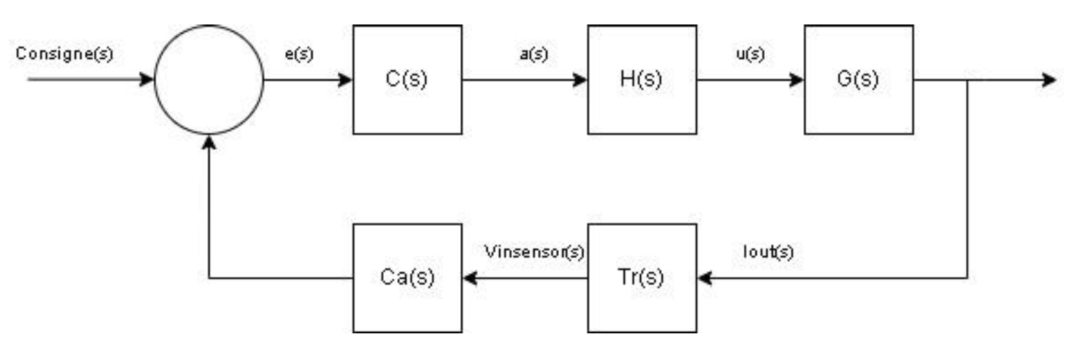
Free Regime
En vert la consigne a appliquer, en jaune le courant dans le moteur.
Deux phases :
Phase un : Le systeme est dans la boucle de regulation, il est en saturation.
Phase deux : La commande ne peut pas atteindre le courant demande car elle ne dispose pas d'une charge suffisante. Le moteur fonctionne donc a une tension de 24 V avec son propre rapport tension/courant.
Reponse indicielle
In green the instruction to apply, in yellow the current in the motor.
Two phases:
Phase one: The system is in the control loop, it is in saturation.
Phase two: The control cannot reach the requested current because it does not have sufficient charge. The motor therefore operates at a voltage of 24 V with its own voltage/current ratio.
Step Response
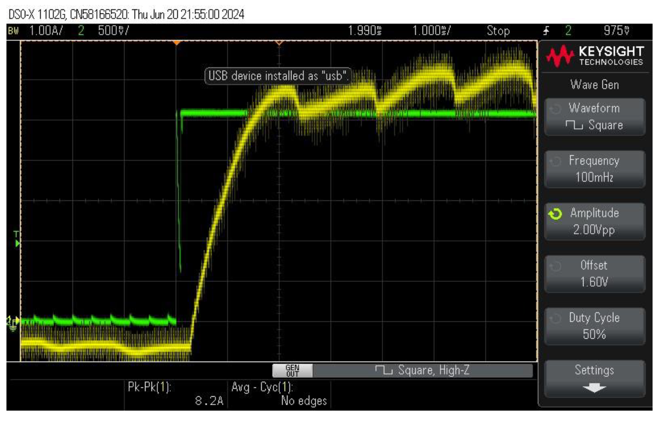
Cela donne un temps de montee d'environ 1.3ms, ce qui est coherent avec les simulations Simulink.
Conception du correcteur PI
Le coeur du systeme de commande est le correcteur proportionnel-integral (PI). La conception du correcteur en boucle ouverte visait a garantir une marge de phase de plus de 45 degres pour assurer la stabilite du systeme. Un modele simple a ete etabli en utilisant la constante de temps electrique et mecanique du moteur, avec des simulations confirmant que les criteres de performance etaient respectes.
Transformation bilineaire
Nous avons ensuite applique une transformation bilineaire pour convertir ce correcteur en une version discrete, puisque le correcteur serait implemente sur un microcontroleur STM32. La frequence de discretisation a ete calculee pour minimiser la perte de marge de phase et s'assurer que les performances en temps discret etaient comparables a la version analogique.
This gives a rise time of approximately 1.3ms, which is consistent with the Simulink simulations.
PI Corrector Design
The heart of the control system is the proportional-integral (PI) corrector. The open-loop corrector design aimed to guarantee a phase margin of more than 45 degrees to ensure system stability. A simple model was established using the electrical and mechanical time constant of the motor, with simulations confirming that the performance criteria were met.
Bilinear Transform
We then applied a bilinear transform to convert this corrector into a discrete version, since the corrector would be implemented on an STM32 microcontroller. The discretization frequency was calculated to minimize the phase margin loss and ensure that the discrete-time performance was comparable to the analog version.
Conclusion
Le projet a permis de developper un systeme de commande fiable et efficace pour un moteur a courant continu, integrant un correcteur numerique qui a ete simule puis implemente sur un microcontroleur. La validation des performances, tant en simulation qu'en implementation reelle, montre que le systeme est capable de reguler precisement le moteur, tout en respectant les contraintes imposees par l'environnement d'implementation.
Ce projet ouvre la voie a des applications industrielles ou un controle precis des systemes electrmecaniques est necessaire, et fournit une base solide pour de futurs developpements vers des systemes plus complexes ou plus optimises.
Conclusion
The project has developed a reliable and efficient control system for a DC motor, integrating a digital corrector that has been simulated and then implemented on a microcontroller. The validation of the performances, both in simulation and in real implementation, shows that the system is able to precisely regulate the motor, while respecting the constraints imposed by the implementation environment.
This project paves the way for industrial applications where precise control of electromechanical systems is necessary, and provides a solid basis for future developments towards more complex or more optimized systems.